A box of electronics arrived the other day, amongst the components was a DFRobot FireBeetle v2 board (DFR0654). An exciting ESP-WROOM-32E MCU device, well made and well priced. However I had a few hiccups getting started, in particular the device was difficult to flash and the built-in RGB LED did not work with the FastLED Arduino library as suggested by the documentation. Information was thin elsewhere on the Internet, so I am sharing what I learned.
TL;DR
- Place a 1uF capacitor between the
RSTpin andGNDpin on the Firebeetle board to reliably flash the device - Use the NeoPixel Arduino Library to get the Firebeetle's built-in RGB to work
Difficulty Flashing the Device
First I followed the instructions on the product wiki. My Arduino IDE was setup correctly, drivers were installed, and the device was successfully connected via serial.
I first tried to flash a hello world program, then I got the following error:
Failed to connect to ESP32: Timed out waiting for packet header
After a lot of investigation I found that despite there being a valid serial connection, the board was inconsistent in its responses. It only returned output on 10% of attempts when running the command esptool.py read_mac:
david@computer:~$ esptool.py read_mac
esptool.py v3.1
Found 1 serial ports
Serial port /dev/ttyUSB0
Connecting........_____....._____....._____.
Detecting chip type... ESP32
Chip is ESP32-D0WD-V3 (revision 3)
Features: WiFi, BT, Dual Core, 240MHz, VRef calibration in efuse, Coding Scheme None
Crystal is 40MHz
MAC: ab:cd:ef:12:34:56
Uploading stub...
Running stub...
Stub running...
MAC: c4:5b:be:8d:b0:ec
Hard resetting via RTS pin...
I had read that some ESP32 devices had a BOOT button and that this should be pressed when flashing the board. The Firebeetle has no such button, however I tried pushing the RST button at random intervals when attempting to flash the device. I had some success with this approach and the board successfully flashed. It was still only working about 10-20% of the time.
I persevered and I cam across this an randomnerdtutorials.com article on how to deal with ESP32 intermittent flashing problems. It suggested placing a 10uF capacitor from EN pin to GND on the ESP32 module. This sounded a little strange and the Firebeetle didn't obviously have the ESP32 EN pin exposed as it's EN pin is used to enable to 3.3V power supply on the board, so I kept looking. Then in the esptool.py wiki, "Boot Mode Selection" notes I saw the same suggestion, this time using a 1uF capacitor. Given I had run out of alternate solutions, I said I'd give it a try.
IT WORKED, SOLVED, SUCCESS, THE SOLUTION
It did work, placing a 1uF capacitor between the RST pin and GND pin on the Firebeetle allowed me to reliably flash the device with a successful response on 100% of attempts.
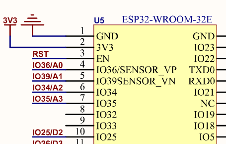
You may have noticed that I have suggested the RST pin and not the EN pin as mentioned in the two articles I mentioned. It took me some time to figure this out. If you look at the FireBeetle board schematic you will notice that the the EN pin on the ESP32 module is connected to RST on the FIrebeetle board. So in the case of the Firebeetle RST = EN.

Built-in RGB LED not programmable with FastLED
It is suggested by the WIKI that the built-in RGB LED (WS2812) on pin 5 is programmable using the FastLED Arduino library. It is not. Anytime I tried to use the library the LED illuminated at full brightness on all three colours. I had no control.
I noticed that on the Firebeetle, the LED was connected via a 3 wire connection rather than the SPI connection that was referred to everywhere in the FastLED documentation. This is similar to the Adafruit NEOPIXEL, and in fact some of the NEOPIXELs use a very similar module, the WS2811. This made me think to try the NeoPixel Arduino Library.
IT WORKED, I installed the library and tried the 'buttoncyler' example, the LED worked perfectly cylcing through all the colours.
Links
- DFRobot FireBeetle v2 ESP32 (DFR0654) board wiki page
- DFRobot FireBeetle v2 ESP32 (DFR0654) board schematic
- esptool.py wiki, "Boot Mode Selection" notes
- randomnerdtutorials.com instructions on how to deal with ESP32 intermittent flashing problems
- Product listing on Core Electronics Australia
Credits
Photo by Stephen Hocking on Unsplash
